Vintage loudspeaker crossovers: what ages, how to test it, and how to recap without changing the sound
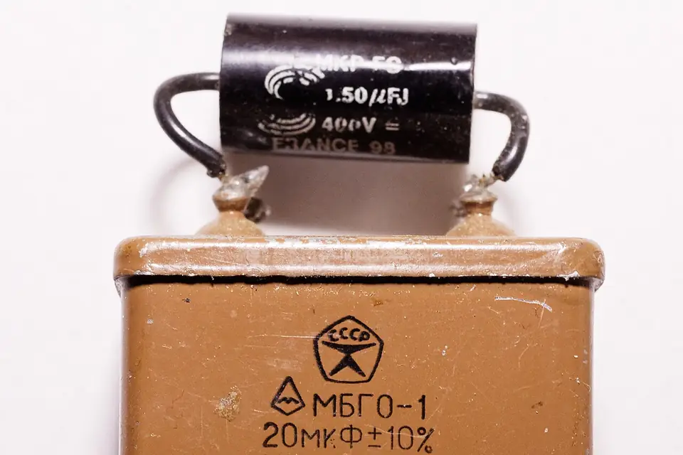
A 1.5 µF polypropylene film capacitor of the kind sold for crossover work, wired across an older paper capacitor. Photo: Retired electrician, Wikimedia Commons, CC0 1.0.
When an old pair of loudspeakers sounds dull, uneven or simply different from one side to the other, the woofer surrounds get the blame first, and often rightly. But behind the drivers, on a small board or glued to the inside of the cabinet, sits a passive crossover: a handful of capacitors, coils and resistors that decides which frequencies reach which driver. Some of those parts age. This guide explains what the crossover does, what actually goes wrong after forty or fifty years, how to check it with ordinary tools, and how to replace parts without quietly turning a classic speaker into a different one.
What the crossover is for
A two-way or three-way speaker uses drivers that each handle part of the audio range: a woofer for bass and lower midrange, a tweeter for treble, sometimes a midrange unit in between. Feeding the full signal to every driver would overload the tweeter with bass and make the woofer beam and break up at high frequencies. The passive crossover splits the amplifier's output so that each driver receives mainly the band it was designed for.
It does this with three kinds of component. A capacitor in series passes high frequencies and blocks low ones, so it sits in front of the tweeter. An inductor (a coil of copper wire, with or without a core) does the opposite and sits in front of the woofer. Resistors reduce the level of a driver that is more sensitive than the others, usually the tweeter. The simplest networks, with one part per driver, roll off at 6 dB per octave; networks with two reactive parts per branch roll off at 12 dB per octave, and steeper designs use more. The exact values were chosen by the designer to suit those particular drivers in that particular cabinet, which is the single most important fact to keep in mind before changing anything.
Many vintage speakers also carry level controls on the front baffle or the back panel, marked "treble", "presence" or with a scale in decibels. These are usually wire-wound variable resistors (L-pads) or switched resistor ladders. Some models add a fuse, a small lamp or a self-resetting device to protect the tweeter from overload.
What wears out, and what does not
Inductors and resistors rarely fail on their own. A coil is a length of insulated wire; unless it has been cooked by abuse, it measures the same today as when it was wound. Wire-wound resistors are similarly stable, though they can crack or come loose from their solder if the speaker was driven very hard.
Electrolytic capacitors are the usual weak point. To get large values cheaply, many manufacturers used non-polarised (bipolar) electrolytic capacitors in crossovers, especially in the woofer's filter and in budget models. Like the electrolytics inside amplifiers, which we cover in what fails in vintage hi-fi, their liquid electrolyte slowly dries out. Capacitance drifts, internal resistance rises, and the crossover point moves. In a tweeter branch, a capacitor that has lost value lets through less of the lower treble; the speaker sounds veiled. Look for bulging ends or a split sleeve.
Film and paper capacitors age far more gracefully. Polypropylene and polyester film types, recognisable by their plastic or wax-dipped bodies, normally stay close to their marked value for decades. Old paper-in-oil types can leak or drift, so they are worth measuring rather than assuming.
Level controls are the most common source of real trouble. The wiper of a wire-wound pot oxidises, and a speaker that has sat with its control at one position for years may play a tweeter at reduced level, crackle when touched, or cut out entirely. This is often mistaken for a dead tweeter.
Joints and wiring also deserve a look. Cold solder joints, push-on connectors that have lost their grip, and glue that has gone hard and pulled on a lead can all cause intermittent faults.
Listen and compare before opening anything
The great advantage of a stereo pair is that you have a reference. Play mono music, or a mono test signal, through both speakers, then swap them left to right so the room does not mislead you. Stand close to each in turn and listen to the tweeter with your ear near the grille. A tweeter that is clearly quieter or duller on one side points to its branch of the crossover, its level control or the tweeter itself.
Before blaming the crossover, rotate each level control fully a dozen times while the speaker is silent and disconnected. That alone often cleans the track enough to restore the treble, and it tells you whether the control is the culprit. Also check the drivers: a woofer with a torn or rotted surround, which we deal with in re-foaming a vintage woofer, changes the bass far more than a tired capacitor ever will.
Measuring the parts
You need a multimeter and, ideally, a capacitance meter or an inexpensive component tester. Disconnect the speaker from the amplifier, remove the drivers or the back panel as the design requires, and photograph the crossover from several angles before touching a single wire. Label every lead.
- Identify the circuit. Draw it, or find it in the service documentation. Our guide to service manuals and schematics explains where those are published legitimately. Note every printed value.
- Measure capacitors out of circuit. Lift one lead of each capacitor, otherwise the coil or driver in parallel will distort the reading. Compare the value with the marking and with the same part in the other speaker. Electrolytic capacitors in crossovers often had wide tolerances when new, so the comparison between the two speakers is as useful as the printed number.
- Measure resistors and coils for continuity. A coil should read a low resistance, typically well under a few ohms; an open circuit means a broken lead or winding. Resistors should be close to their marked value.
- Check the level control for a smooth resistance change across its travel, with no jumps to infinity.
Replacing capacitors without changing the voicing
The rule is simple: replace like with like in value. If the original is a 4.7 µF part, fit a 4.7 µF part, with a voltage rating at least as high as the original. Where a precise value is not available, two capacitors in parallel add up (2.2 µF plus 2.2 µF gives 4.4 µF), which is how many builders reach odd values.
Whether to replace a non-polar electrolytic with a film capacitor is a matter of judgement. Film parts are more stable and last longer, and in a tweeter branch, where values are small, they are inexpensive and fit easily. Two cautions apply, though. First, film capacitors of large value are physically big, and must be mounted securely so they do not rattle against the cabinet. Second, an aged electrolytic also contributed a little series resistance, which the designer may have counted on. Swapping it for a near-ideal film part can make the tweeter slightly brighter than it was. If the result sounds harsh, a small series resistor can restore the balance, but that is a decision for someone willing to measure, not to guess.
Things not to "upgrade"
- Coil values and positions. Moving an air-core inductor closer to another, or turning it, can change the coupling between them. Mount replacements in the same place and orientation.
- Crossover frequencies. Changing values to "extend the treble" alters the designer's balance and can put a tweeter at risk by sending it more low-frequency energy than it can handle.
- Tweeter protection. If the original had a fuse or protective lamp, keep it, and replace a fuse with the same rating.
- Wiring polarity. Many crossovers deliberately connect the tweeter in reverse polarity. Copy the original connections exactly rather than "correcting" them.
Testing after the work
Reassemble, then play quiet mono music and compare the two speakers again at your listening position and up close. If a buzz appears only at certain notes, look for a loose part touching the cabinet. If one speaker is still different, re-measure: a capacitor fitted to the wrong branch, or a coil connected to the wrong terminal, is easy to miss. If the system hums rather than buzzes, the problem lies elsewhere in the chain; our method for tracing hum and buzz starts at the amplifier.
A crossover is one of the gentlest jobs on the bench: low voltages, no mains wiring, and a twin to compare every part with. Done with photographs, a meter and the original values, it lets a tired pair sound the way its designers intended.
Sources
- Passive crossover principles, filter orders and slopes, and the role of capacitors, inductors and resistors: Wikipedia, "Audio crossover".
- Non-polarised electrolytic capacitors, electrolyte drying and ageing: Wikipedia, "Aluminum electrolytic capacitor".
 On the bench
Re-foaming a vintage woofer
Crumbling foam, the right replacement ring, voice-coil centring and a rub test: a patient repair that saves many good speakers.
 On the bench
What fails in vintage hi-fi
Capacitors, pots, relays, belts and bias, and why safety comes before any of them.
 On the bench
Tracing hum and buzz
Hum or buzz, amplifier or source, ground loop or failing part: an order of tests that finds the culprit without touching the safety earth.